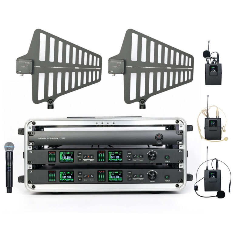
 Wireless Microphone + RF Amplifier System Kit, Professional Stage Equipment
Home
/ Products
/ Wireless Stage Microphones
/ Radio Frequency Signal Amplification System for Wireless Microphone
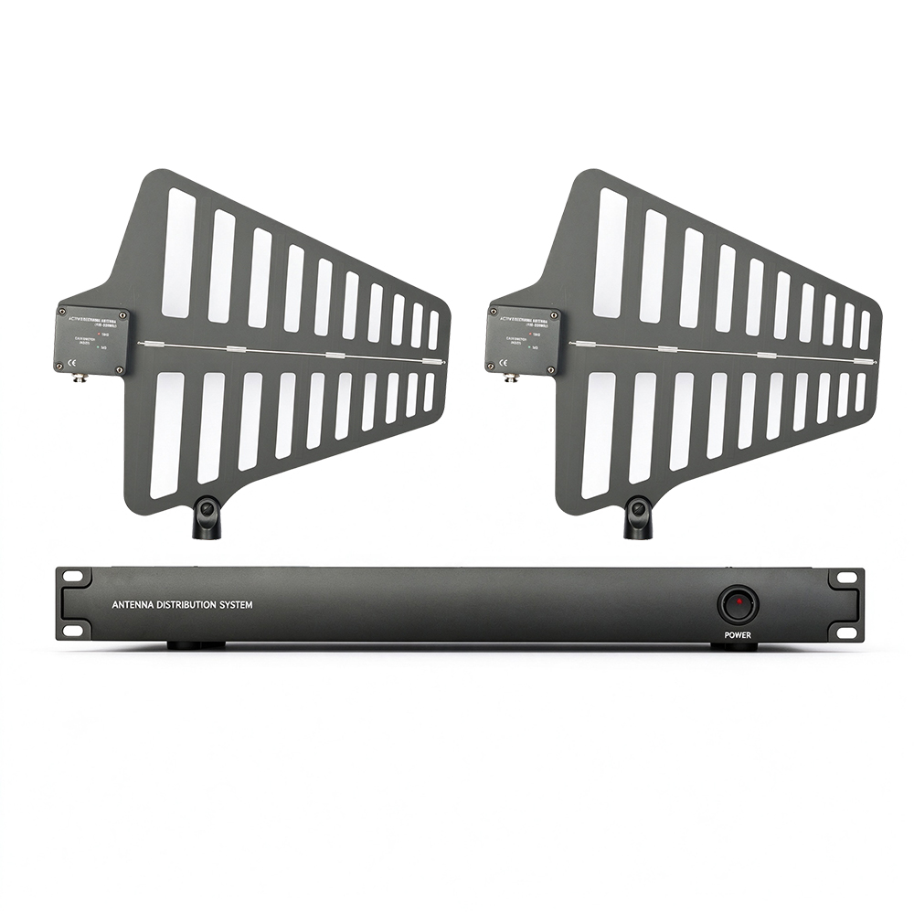
Radio Frequency Signal Amplification System for Wireless Microphone
Antenna
Brief Description
This log-periodic dipole array provides optimal reception when aimed at the intended coverage area. The integrated amplifier features two gain settings to compensate for different levels of coaxial cable signal loss. The antenna can be mounted on a microphone stand, hung from the ceiling, or fixed to a wall with the integrated rotating bracket.
Features
- Low-noise signal amplifier compensates for insertion loss of coaxial cables
- Compatible with wireless receivers and antenna distribution systems that supply 10–15 V DC
- Integrated threaded bracket allows easy mounting onto microphone stands
- High quality, high reliability and durability
Installation
- Connect the antenna to the receiver or distribution system using antenna cable (or any 50-ohm low-loss coaxial cable).
- The antenna shall only be used with receivers or distribution systems that provide 10–15 V DC power.
- Reduce the gain setting for short cables; increase the gain setting for long cables. Please note that signal loss depends on both cable quality and cable length.
- A lightweight 50-foot cable may require higher gain than a 100-foot low-loss cable.
- Aim the antenna toward the coverage area.
Antenna Placement
Observe the following points when fixing the antenna:
- The antenna and receiver must operate on the same frequency band.
- Mount antennas at least four feet apart from each other.
- Adjust antenna position so that the transmitter has a clear line of sight without obstacles (including audience).
- Keep the antenna away from large metal objects.
Important Note: Before the wireless system is used for speeches or performances, perform a walk test to check signal coverage. Test different antenna positions to find the optimal placement. Mark dead spots according to actual conditions and remind speakers or performers to avoid these areas.
Gain Setting
Gain is only intended to compensate for calculated cable signal loss. Higher gain does not deliver better RF performance. Excessive gain will actually reduce reception range and available channels. The receiver achieves optimum performance when the sum of signal gain and cable loss equals 0 dB. Higher gain amplifies all signals within the frequency band, including interference and ambient RF noise. It cannot selectively boost the transmitter signal.
- Based on the RF indicator or level meter reading on the receiver, use the lowest gain setting that achieves good RF reception of the transmitter.
- If the antenna RF Overload indicator lights up, reduce the gain.
- For applications with cable length ≤ 6 m and distance between transmitter and antenna less than 30 m, use the 3 dB gain setting.
- Recommended Gain Settings
Note: For installations where the distance between antenna and transmitter is less than 30 m, reduce the gain setting by one level.
Antenna
Brief Description
This log-periodic dipole array provides optimal reception when aimed at the intended coverage area. The integrated amplifier features two gain settings to compensate for different levels of coaxial cable signal loss. The antenna can be mounted on a microphone stand, hung from the ceiling, or fixed to a wall with the integrated rotating bracket.
Features
- Low-noise signal amplifier compensates for insertion loss of coaxial cables
- Compatible with wireless receivers and antenna distribution systems that supply 10–15 V DC
- Integrated threaded bracket allows easy mounting onto microphone stands
- High quality, high reliability and durability
Installation
- Connect the antenna to the receiver or distribution system using antenna cable (or any 50-ohm low-loss coaxial cable).
- The antenna shall only be used with receivers or distribution systems that provide 10–15 V DC power.
- Reduce the gain setting for short cables; increase the gain setting for long cables. Please note that signal loss depends on both cable quality and cable length.
- A lightweight 50-foot cable may require higher gain than a 100-foot low-loss cable.
- Aim the antenna toward the coverage area.
Antenna Placement
Observe the following points when fixing the antenna:
- The antenna and receiver must operate on the same frequency band.
- Mount antennas at least four feet apart from each other.
- Adjust antenna position so that the transmitter has a clear line of sight without obstacles (including audience).
- Keep the antenna away from large metal objects.
Important Note: Before the wireless system is used for speeches or performances, perform a walk test to check signal coverage. Test different antenna positions to find the optimal placement. Mark dead spots according to actual conditions and remind speakers or performers to avoid these areas.
Gain Setting
Gain is only intended to compensate for calculated cable signal loss. Higher gain does not deliver better RF performance. Excessive gain will actually reduce reception range and available channels. The receiver achieves optimum performance when the sum of signal gain and cable loss equals 0 dB. Higher gain amplifies all signals within the frequency band, including interference and ambient RF noise. It cannot selectively boost the transmitter signal.
- Based on the RF indicator or level meter reading on the receiver, use the lowest gain setting that achieves good RF reception of the transmitter.
- If the antenna RF Overload indicator lights up, reduce the gain.
- For applications with cable length ≤ 6 m and distance between transmitter and antenna less than 30 m, use the 3 dB gain setting.
- Recommended Gain Settings
Note: For installations where the distance between antenna and transmitter is less than 30 m, reduce the gain setting by one level.
Specifications
- Frequency Range: 400 MHz–950 MHz
- Reception Angle: 70°
- Gain: Built-in 3 dB / 10 dB adjustable
- Connector: BNC
- Impedance: 50 Ω
- Voltage: 9–12 V
- Dimensions: 360×330×35 mm
Directional Antenna (External 31-level adjustable gain)
Specifications
- Frequency Range: 400 MHz–950 MHz
- Reception Angle: 70°
- Gain: External 0 dB ~ +31 dB adjustable
- Connector: BNC
- Impedance: 50 Ω
- Voltage: 9–12 V
- Dimensions: 360×330×35 mm
No reviews yet. Be the first to review this product.
You may also like
Wireless Microphone + RF Amplifier System Kit, Professional Stage Equipment
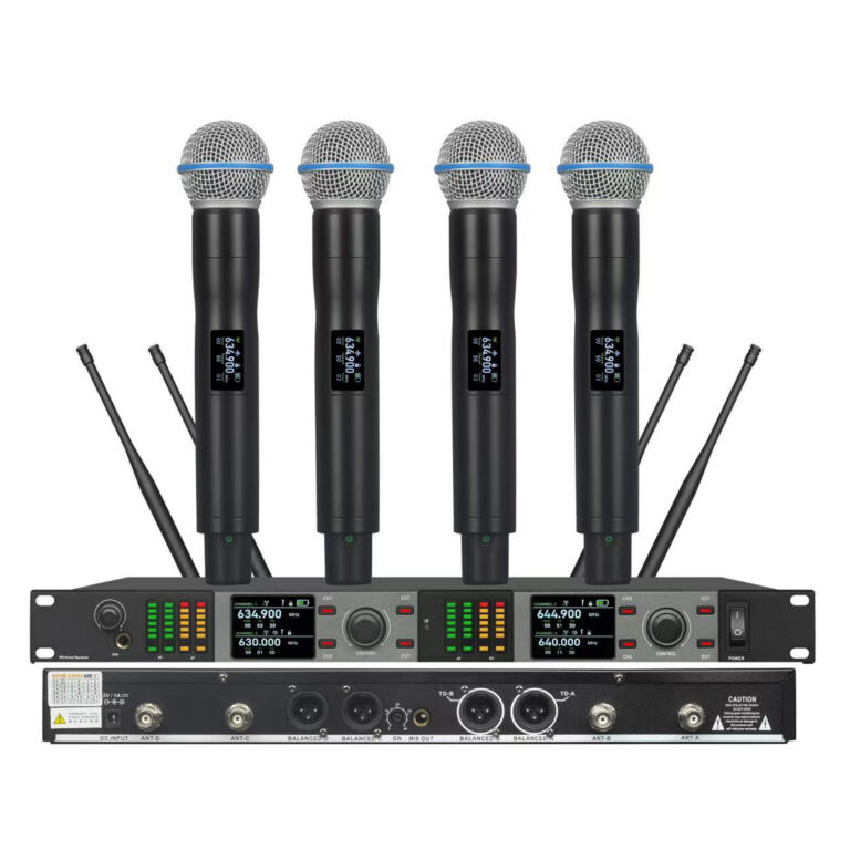 G24-4 Wireless Microphone System 4 Channel for Stage Performance
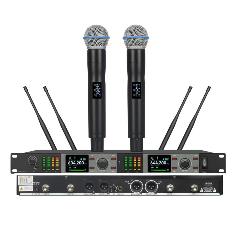 G24-2 Wireless Microphone System 2 Channel for Stage Performance
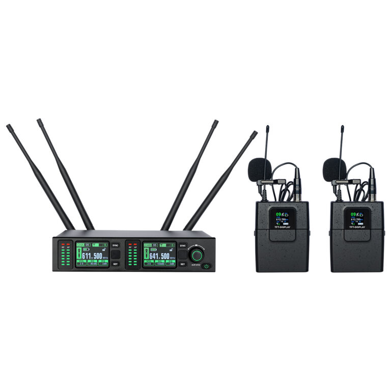 G2 Lavalier Wireless Microphone System for Stage Performance
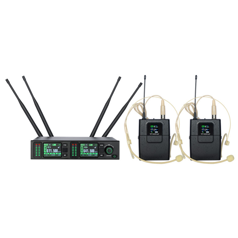 G2 Skin-colored over-ear headset Wireless Microphone System for Stage Performance